.jpeg)

 |
| by Rachel Parker-Stephen |
An artist friend suggested we work together to make centerpieces for tables at a celebration for our senior pastor, who is a certified yoga instructor. It would be a minimalist portrayal of a person in a seated yoga pose. She provided the profile as a single pen stroke.

I cleaned up the scanned image and made it more solid black, then imported it as a SVG file into Fusion 360. I extruded it and figured out how large I could make it and still fit into the portion of my print bed that heats well.

I found that some areas still did not stick well, so I added custom rafts. That helped... then I looked back at my records and found that my temperatures were quite a bit lower than I had used on that filament before. So I brought up the temperature and it stuck even better.

The bottom curves of the design included some flat areas so it would be relatively stable, but it was still easy to knock over. So I designed a round base with tabs that the upright part would snap into with a friction fit.

Here is the finished print. I made 12 sets.

 |
| Photo by Chie Chap |

A sample part printed with a 0.25mm nozzle came out rather lumpy, so I wanted to use my smallest nozzle, 0.15mm. I've used it before, but it's so small it can be finicky. My previous project was printed in Nylon, which takes a lot of heat... and can be hard to clean out of the hotend. Sure enough, it caused the worst clogs I've ever seen. I could sometimes get some cleaning filament through, but it would repeatedly gum up again. The 0.25 nozzle was clogged and I had to use a heat gun and some very small cleaning wires to get it clear. Then the "heat break" portion of the hotend was also clogged. I had to use a drill bit and some careful hammer taps to get it cleared.
I finally figured out that the hotend was not getting as hot as it used to, barely reaching the temperature needed to melt the Nylon. So there was not enough heat to permeate the whole hotend and nozzle, which explains why I could not get it cleaned out well. Fortunately I also have some 0.15mm cleaning wires, which are really hard to insert. I finally got it working well enough to get residual PLA out of the 0.15 nozzle and do some test prints.


A friend was painting and recarpeting some bedrooms, and each room had the same style of sliding closet doors. He found that the plastic spacers or guides on the top of the doors had deteriorated and needed to be replaced. Do you know how many different manufacturers there are for home products? Lots! Do you know how many of them are still in business and supplying spare parts? Almost none! The guy at the hardware store just shook his head.
This is the same friend who specified the custom electrical box last year, so he thought Aha! Roger could make them. In fact, this is exactly the kind of project that got me interested in 3D printing in the first place: making irreplaceable parts. He's an engineer, so he carefully measured the old parts and gave me a detailed drawing.

I decided to print them in Taulman Bridge Nylon, because it is tough (resisting wear) and relatively low friction for moving parts.
I printed about three cycles of samples, refining the width of the insert part and the guide part.
He needed 12 parts: 2 ends x 2 doors x 3 rooms. As with the previous project, I used Simplify3D's Sequential Print to produce several units per print job. Because the Nylon requires high heat I avoided the cooler areas of my heated bed.

I was approached by the head custodian at our church about 3D printing some parts. On the back of every pew there are several wooden holders with room for books, papers, pencils, and holes to receive 4 empty communion cups. You know those little glass or plastic cups? Each of the 4 cup holes has - or had - a plastic insert. I think the main purpose is to soften the noise of the cup being set down, and maybe prevent the glass (in the old days) from being scratched by the wood? Whatever, the plastic had deteriorated over the years and many of the inserts had broken and been discarded.
Simplest design ever! It's just a cylinder about 3/4 inch high, with a flange on top. I printed a few samples, varying the cylinder outside diameter by a millimeter. We tested them for fit and picked the right size. The holes in the wood were quite consistent.
I needed to print about 200 units. Simplify3D has a feature which can print multiple units in order, rather than printing all the units at one time, one layer at a time. This eliminates the stringing that would occur if the head repeatedly moved from part to part. You have to create a "Process" for each unit you want to print, then select them all to be printed, then choose Sequential Printing. You need to space the parts out enough that the components of the printer's hotend will not hit any previously printed units. In this case the parts are not very tall, so it is a pretty easy layout. I was able to print 16 units per print job.

I had some brown PLA on hand which blended perfectly with the wood color. Each job took just under 3 hours. They all printed very cleanly and needed no post-processing. I delivered them over a couple of weeks and the whole set cost about $12.
At my church we are installing electric door openers on 4 entrances, to make them more accessible to people with wheelchairs, electric convenience vehicles, and walkers. The openers (actuators) from the outside will be wireless, so they can be surface-mounted anywhere. For a couple of the doors there will also be a "hold-open" timer on the inside, so if someone needs to make several trips (or whatever), they can turn the knob on a timer for up to an hour. That timer is wired to send a low-voltage signal to the controller, so it needs to be mounted where wires can be run and hidden. And there will also be a shutoff switch to disable the opener from the inside (not sure why, but OK), which is also a low-voltage signal, not a power switch.
The main entry is big glass windows and doors between aluminum uprights. The best place for the timer/switch combo is on the side of one of those aluminum uprights, which is also how we're getting power to the opener and controller. The corner between the upright and the glass is pretty shallow, and any box will be visible from the outside. Our electrical engineer member (lucky us!) could not find an appropriate box of the right size, with the right mounting holes and wire holes, that would be blend in with the aluminum structure. So he asked if I could 3D print a custom box. Challenge accepted!
He gave me the timer knob and the toggle switch. I took basic measurements of the aluminum upright to set the box depth and designed the box in Fusion 360. I have some silver PET-G which will blend pretty well with the aluminum (it'll mainly be visible through the glass, so the color's not critical). I found a nickel-finish cover plate which will also blend pretty well, and set the box width from it.


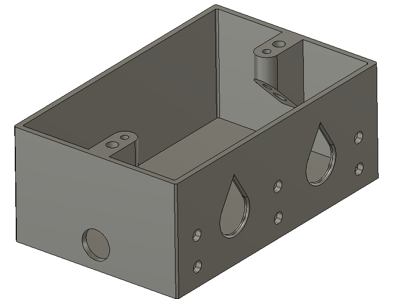
It will need big holes in the side to run the wiring from the post, and a 1/2" hole in the bottom for the cutoff switch. The obvious way to print it is on its back, so the back of the box is fully supported and the sides can print vertically. That means there will be several vertical holes which make overhangs. The side mounting holes are small, so bridging them is not a problem. The hole for the switch is 1/2" and I found that it prints fine, just a tiny droop. The bigger holes for the wiring (think conduit connectors) are a bigger problem. I read about a trick to make the tops of the holes 45-degree triangles, which won't slump, so essentially the holes are teardrop-shaped. Since they'll be hidden, the shape won't matter, and even if the installer wants to put conduit grommets or strain reliefs in, two-thirds of the hole is standard size and should work. I rounded off the edges in case they don't.

I made the entire design parametric because... well, I do them all that way when possible. And since the job site is a few miles from my home, I wanted to minimize the number of fitting trials. It took 34 dimensions to fully specify the design. The tricky part of parametric is making sure that dependent dimensions depend on the right prerequisites so it will scale correctly.
I used mirroring on the side sketch to duplicate the mounting holes around center lines. There's just one central hole and one side hole based on dimensions, and the rest are reflected. The screw pillar is mirrored too.

Here's the overall design:
To get smooth holes and a nice finish I chose a 0.25mm nozzle. The first time I printed with the PET-G there were a lot of globs, scorches and strings. It turns out I had not tightened the nozzle onto the hot end all the way. That let a tiny amount of filament leak out, dribble down, scorch and get all over the print. Once I tightened that down, the surface came out silky smooth and the strings were gone.


The local dealer wanted $80 for the part. Auto parts stores don't stock it. No Internet vendors carry that exact part, and they wanted $50-$60 for similar parts for other models. So I decided to try to fix it.
What broke was a kind of claw that went under the shaft, from left to right in this picture. I did not think I could replicate that exactly with the required strength.


PLA wouldn't do because it's not terribly strong and does not tolerate heat. Nylon is tougher and more heat tolerant, and is somewhat bendable and resilient. (See my bicycle part.) I have a spool of Taulman Bridge Nylon which should do well. Here's an article about printing with nylon.
I used a 0.25mm nozzle because these dimensions are pretty small. The key point was to make the T-post and the D-post just the right size to fit tightly, but be removable for future blade replacement. I designed this parametrically in Fusion 360, and I defined a "tolerance" added to the dimensions of each post. That makes it easy to tweak the size. I printed just one half of first unit so I could clearly see how the posts lined up. Then I printed four iterations getting the sizes just right so they would fit with just the right friction. The filament cost per part was about 8 cents, and it took 30 to 40 minutes to print, so no big deal to try a few times getting it right.
The picture shows a lot of stringing, typical of nylon in my experience. That really does not matter for this application so I did not work hard at cleaning them off. Usually I use a metal bit in a Dremel tool to clean up, but it really doesn't work on nylon. So I just snipped the worst and left the rest.
Printing it as shown, the posts were prone to layer separation. I did not want to try to print it on its side and deal with support. I counteracted the layer issue with three methods:


And here it is installed on the car. The base is only a few millimeters thick, so it doesn't get in the way of anything.
The total material cost was about 35 cents. Much better than $80 for a whole new arm!
UPDATE: It didn't work. The next time she drove through the car wash, the force of the brush mechanism popped it right out of the arm. I ended up buying a whole new arm.
Another approach is to take a picture of the image produced by an eyepiece, which magnifies the image. The amount of magnification depends on the focal length of the eyepiece and the distance in front of and behind it. I have not yet determined this for my adaptor, but probably will at some point.
There are various focal length and magnification calculators available, but they seem to vary and will depend on measuring the actual distances resulting from the adapters. (I'm starting with a 15mm Plössl eyepiece, and I also have a 6mm to work with... they are not the same physical size.)


Next is a tube which inserts into the 1.25" opening and holds the eyepiece at some distance up from it. So that tube is slightly larger than the eyepiece and contains a shelf so the eyepiece rests at the right height. The outside dimension therefore depends on the specific eyepiece to be used. I'm using an SVBony eyepiece, so I measured that carefully. Maybe in the future I can make it larger to accept others. But since the design is all parametric, other users could resize it if needed.


The inner and outer tubes need to slide snugly but smoothly over each other, so they need to fit well. Due to shrinkage of the PLA plastic I used, it took me several iterations of adjusting a tolerance variable before these fit properly. Here is how all the parts appear together, in cross section:

And visualized:

And in real life:

Because the M43 bayonet connector has a lot of fine details, I used my smallest nozzle on the previous design. It's 0.15mm. Unfortunately after printing a few parts it became hopelessly clogged. I went down a rabbit hole trying to unclog it with solvents. Since that was taking a long time, I tried printing with a 0.25mm nozzle, and it worked fine too on the M43 as well as the threads. It's maybe a little more rough, but it works. In the meantime I ordered another 0.15mm nozzle and some 0.15mm cleaning wires.
If the tubes are not set to the right length, the image is highly vignetted, i.e. a small round image in the middle of the camera sensor, highly distorted. By extending the tube the image gets larger and less distorted, until it becomes a usable image. I'll need to do some tests to see if the distortion completely straightens out or remains an issue to deal with in post-processing.
This tube will bear the weight of the camera and needs to be robust enough to not allow it to bend or fall. The thicknesses of the inner and outer tubes are parameters so I can thicken them if necessary. It seems to me that on the one night I have tested it, there was one part that I felt needed to be thicker so that a set screw would not distort it. I think it was the insert on the lower tube, that goes into the telescope focuser. I'll have to check on that again.
The good news is that the adapter did work as intended. The bad news is that I had tracking problems with my telescope's computer, so I was not able to get any useful images. I've taken some steps to improve that, and have some more testing and calibration to do. I also need clear skies and decent temperatures to do some further tests. I'll update this article as I get more results.
These parts and the Fusion 360 design file are now published at https://www.thingiverse.com/thing:4834778
Another step will be to figure out the length needed to make a lower tube for my 6mm eyepiece, which is considerably longer than the 15mm. The length of the adapter may increase the leverage that the weight of the camera places on the telescope tube, which may change the power that the telescope drive motors need to exert to move the whole assembly. We'll see how that goes.
This was a really quick design, perfect for 3D printing. We have some booklets that are too small to stand up on a shelf on their own, and it would be great to stick them in a notebook. Imagine something that was printed on 11"x17" paper and then staple-bound in the middle to make an 8.5"x11" booklet. My wife was familiar with a product made for holding magazines or brochures in a notebook, and found and example on line. A simple sketch-extrude project in Fusion 360. I designed and printed one, then decided we could print it thinner and make some cutouts to save time and plastic.


I had developed an adapter to attach my Olympus camera to my Meade reflecting telescope and shared it on Thingiverse. It worked, but a user noted that it would attach more securely to the camera if the entire Micro Four Thirds bayonet connector was used. The mechanism of the MFT camera needs holes in the outer parts for the pin to latch into. I had reduced it to just the interior part, mainly to get the camera closer to the scope so it would focus properly.

I've had some experience with printing very fine parts with a 0.15mm nozzle and very small layer height, so I though I might be able to print the MFT camera adapter accurately enough for the latch to work. I took another look at the MFT file I had downloaded from Salvaged Circuitry and figured out how to lower it. I also took careful measurements of the new eyepieces and shortened the focuser part, so the eyepieces and camera would be at the right focus distance to work. So this project ended up as a total redesign.
I was able to measure the telescope focuser threads with a thread gauge. The screws I used are a common size with National Coarse threads. Neither of these thread sizes were available in Fusion 360's thread library, so I had to create custom threads using the Coil function. They all fit great.
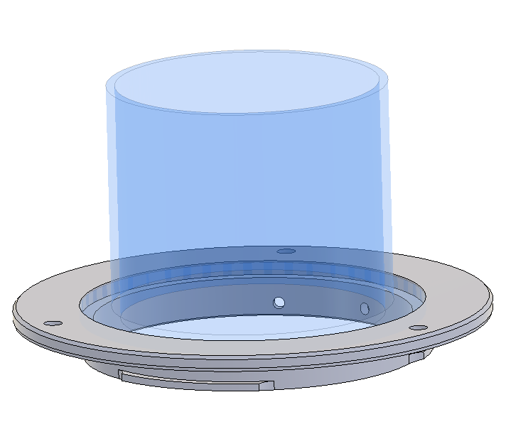
The tricky part is that if printed normally, both the focuser adapter and the camera adapter would need to have overhangs, and I really did not want supports roughening up the surfaces. So I figured out how to design each of these adapters in two parts that I could glue together. This actually worked very well, and enabled me to prototype and fine-tune each of the four parts separately, reducing waste.
Here is the part that screws onto the telescope focuser. The blue and gray parts are printed separately, so no overhang occurs. The screw holes with threads print horizontally but are small enough that no sag occurs and no support is needed. The big gray part is printed as shown, so its flange and threads do not experience overhang. These two overlap a bit and are glued together as shown.