At my church we are installing electric door openers on 4 entrances, to make them more accessible to people with wheelchairs, electric convenience vehicles, and walkers. The openers (actuators) from the outside will be wireless, so they can be surface-mounted anywhere. For a couple of the doors there will also be a "hold-open" timer on the inside, so if someone needs to make several trips (or whatever), they can turn the knob on a timer for up to an hour. That timer is wired to send a low-voltage signal to the controller, so it needs to be mounted where wires can be run and hidden. And there will also be a shutoff switch to disable the opener from the inside (not sure why, but OK), which is also a low-voltage signal, not a power switch.
The main entry is big glass windows and doors between aluminum uprights. The best place for the timer/switch combo is on the side of one of those aluminum uprights, which is also how we're getting power to the opener and controller. The corner between the upright and the glass is pretty shallow, and any box will be visible from the outside. Our electrical engineer member (lucky us!) could not find an appropriate box of the right size, with the right mounting holes and wire holes, that would be blend in with the aluminum structure. So he asked if I could 3D print a custom box. Challenge accepted!
He gave me the timer knob and the toggle switch. I took basic measurements of the aluminum upright to set the box depth and designed the box in Fusion 360. I have some silver PET-G which will blend pretty well with the aluminum (it'll mainly be visible through the glass, so the color's not critical). I found a nickel-finish cover plate which will also blend pretty well, and set the box width from it.


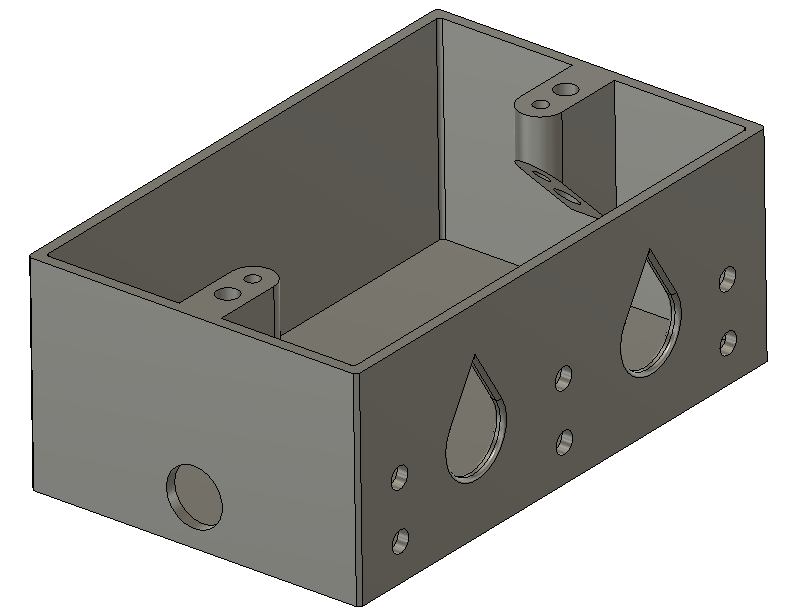
It will need big holes in the side to run the wiring from the post, and a 1/2" hole in the bottom for the cutoff switch. The obvious way to print it is on its back, so the back of the box is fully supported and the sides can print vertically. That means there will be several vertical holes which make overhangs. The side mounting holes are small, so bridging them is not a problem. The hole for the switch is 1/2" and I found that it prints fine, just a tiny droop. The bigger holes for the wiring (think conduit connectors) are a bigger problem. I read about a trick to make the tops of the holes 45-degree triangles, which won't slump, so essentially the holes are teardrop-shaped. Since they'll be hidden, the shape won't matter, and even if the installer wants to put conduit grommets or strain reliefs in, two-thirds of the hole is standard size and should work. I rounded off the edges in case they don't.

I made the entire design parametric because... well, I do them all that way when possible. And since the job site is a few miles from my home, I wanted to minimize the number of fitting trials. It took 34 dimensions to fully specify the design. The tricky part of parametric is making sure that dependent dimensions depend on the right prerequisites so it will scale correctly.
I used mirroring on the side sketch to duplicate the mounting holes around center lines. There's just one central hole and one side hole based on dimensions, and the rest are reflected. The screw pillar is mirrored too.

Here's the overall design:
To get smooth holes and a nice finish I chose a 0.25mm nozzle. The first time I printed with the PET-G there were a lot of globs, scorches and strings. It turns out I had not tightened the nozzle onto the hot end all the way. That let a tiny amount of filament leak out, dribble down, scorch and get all over the print. Once I tightened that down, the surface came out silky smooth and the strings were gone.


