Saturday, December 1, 2018

Elephant cutlery drainer

Between the product design, the 3D modeling, and the printing, I learn one or more new topics with every project. I worked on this one for more than a month. New tools and techniques included:

  • Initial drawings on iPad with Apple Pencil and Autodesk SketchBook
  • iPad connected to Mac as graphics tablet with Duet
  • Fusion 360's Spline curves
  • Fusion 360's Shell command
  • Fusion 360's Loft command options
  • Fusion 360's Sculpt mode
  • Printing big

Concept & Design

I was looking for a bigger project to print. Most of my projects have been just a few inches in size. But printing large solid objects can take a long time, and as a hobbyist there are limits on the time I can spend babysitting large prints. So I was thinking about large hollow products when I encountered this elephant-shaped cutlery drainer on Thingiverse. It's a useful product, if a bit silly. Water from the draining items shoots from the elephant's trunk into your sink. But I didn't really like the angular appearance of the "low-polygon" method.


I spent a few hours among Asian elephants on a safari in Sri Lanka this year, and elephants have been on my mind. So I decided to try a more realistic, but still stylized, version of the elephant drainer.


Design considerations included:

  1. A large top opening to handle a realistic number of cutlery items
  2. Possibly a divided interior so items would not lay over too much
  3. Low center of gravity and/or wide stance so top-heavy objects would not tip it over
  4. On a real elephant, the trunk starts high on the face and goes downward. In this drainer, the water is going to come from the bottom tips of the objects. The water can't flow up to enter the trunk, so the body and face design needs to give the illusion of a trunk while letting the water enter the bottom of the trunk.
I did not know how I would possibly sculpt the thing from scratch, and most objects I've designed have been basically geometrical, so I envisioned virtually "carving" the body and head from a solid core by cutting it from the side, top, and front using profiles. 


Concept art

I've been playing with Autodesk's SketchBook and Apple Pencil, so I used it to draw multiple profiles. For the top and front profiles I used its mirror function to get a symmetrical profile. I knew that in Fusion 360 I would probably design one side and then mirror the solid object, so I didn't really *need* full drawings, but drawing both sides of the profiles helped make sure it was going to be attractive and what I envisioned.
Side view

Top view. Note that the legs stick out a bit from the body.


Head front view


Rear view


Version 1 - Carved from Three Profiles


I imported the drawings into Fusion 360 and used Spline curves to reproduce them as sketches to use to cut virtual blocks in three directions to form the body, head and trunk. I tried the "duet" application to draw on my iPad as a connected tablet, but ultimately it was easier to use the mouse on the big screen.


I learned to use the Shell feature to hollow out the combined shapes. I added a 5-degree sloped floor and ensured a hole was drilled through the trunk.


I used the Loft feature to join elliptical shapes to form the front and back legs.


I created the whole thing small, so I could print samples relatively quickly. (This elephant is apparently not afraid of mice.)

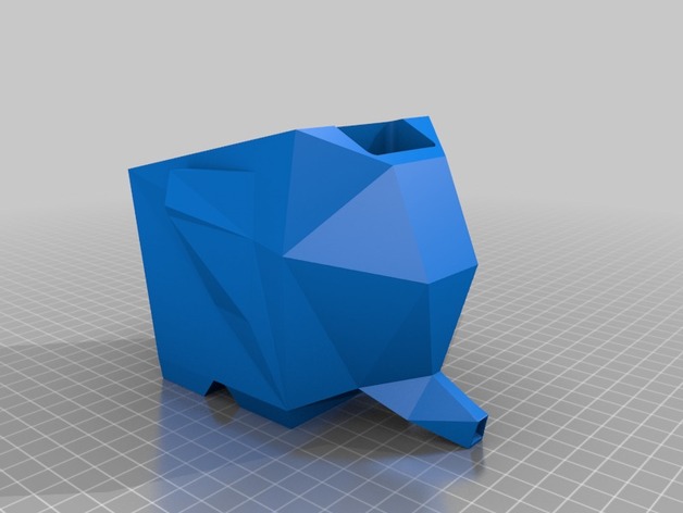
Ultimately I did not like the result. It was too angular - you can see how the body has places where two different curves join. And there's an artificial-looking "web" under the trunk.

The other problem was that the Shell command has trouble with shapes that have too many complex curves joining. It ultimately failed with my model. So I started over.

Version 2 - Combined Sculpted and Math

I spent some time learning about Fusion 360's Sculpt mode, which works by modifying 3D forms, rather than extruding them from sketches and cutting things. I started with two spheres and pushed and pulled them into more organic shapes for the body and head.

I combined them with mathematical shapes for the legs and trunk.


I also lowered the body closer to the ground to reduce the amount of support material that would be needed.


I didn't like this result either. The short legs and trunk made it look more like a pig than an elephant. So back to the drawing board.


Version 3 - Combined Sculpted Shapes

I thought about making realistic legs to convey the elephant-ness, but bent so the belly would still be on the ground. I found a variety of artwork and sculpture depicting elephants kneeling, and then produced this sketch based on them.

Back in the Sculpt mode, I learned to stretch and bend cylinders: with a single bend for the back leg, and with two bends in the front leg so the foot would be flat on the ground. The legs intentionally crowd the face.


Another cylinder was the basis for the trunk. It's wider at the top and stands out a bit from the face.


I pushed some little dents into the top of the trunk to make it wrinkly-flexible looking. (I got this idea from how they put finger grips in a knife handle in an Fusion 360 instructional video.) You can see that in this shot of the full-size final product being printed.

Here you can also see the support material around the belly, under the legs, and under part of the trunk.


For the eye I went back to how a real elephant looks. I had taken this extraordinary shot of a wild elephant in Sri Lanka.


I traced over the eye in Fusion 360 and turned it into a reverse extrude, essentially a cutout. The shell is thin enough, and the cut deep enough, that it's actually open in places and lets light shine through.


Here's the finished small-size half-body test print. Printing a half-body sample is a great way to see how it's really going to work internally, how things are going to fill in, etc. You can see how I filled in the bottom of the body and trunk with a 5-degree slope for water to flow out.


The Final Print


During the design I had worked with convenient measurements, knowing I could scale it up to maximum size in the slice-print software. I placed it diagonally on the print bed to get the maximum length from legs to trunk. I scaled it up by 210%, resulting in almost 10" total length. The shell started out 0.2 cm thick, so after scaling it is 0.42 cm thick, which is just about right. There's a tradeoff: too thin would not be stiff enough, too thick will increase the print time. This was by far the biggest thing I've ever printed. It took nearly 18 hours!

I chose PET-G filament because it's food-safe, and found a really nice silver-gray.

Unfortunately I forgot one thing: my print bed doesn't heat evenly, plus I think I didn't put enough hairspray at the the very back. So the left rear foot failed to adhere perfectly and curled up. I didn't see it until it was all done, or I might have started over. (Support material is still attached in this shot.) With a little grinding of the irregular parts, it came out OK, it's just kind of lifted in the air.

I also forgot to add a tail!


Here's how it looks in use, with the trunk out over the sink:


I had thought ahead and added slots on the sides to allow for a removable divider, printed separately. This allows objects to stand up straighter.


The divider doesn't go all the way to the bottom, so it doesn't obstruct the drainage.


All in all, I'm quite pleased with how it came out, being my first sculpted project and my first really big print. This is about as big as my Robo3D R1+ can go. Lots of people saw it at our house at Thanksgiving and a couple people asked for copies for Christmas... but at 18 hours per part that may not happen. It's definitely an iterative process. Fortunately printing small-size models saves time and plastic.

I published the design files on Thingiverse here. In the first two weeks over 400 people have downloaded it, but no one has posted a print yet.


Saturday, June 30, 2018

Dungeons & Dragons dice in wood

One of my girls asked if I could make her a set of Dungeons & Dragons dice. Not knowing anything about them, I sent her shopping on Thingiverse and she settled on this set designed by JakeVav. I printed it in Hatchbox Wood PLA hybrid so I could make it look antique-y.

No, I didn't print them all at once, this is a reunion photo. I tried to print them in groups of 2 or 3 to save setup and print time, but I found that as the extruder jumped from one die to another the filament sagged out of the nozzle and left a little "worm" on the next die. Although I experimented with retraction, coast and wipe settings, the wood filament is just more prone to this side effect. So I reprinted the last few as singletons and they came out much cleaner.

After some cleanup I treated them all with wood stain (submerged for several hours) and added a couple very thin coats of Varathane. They came out pretty darn wood-like, especially the triangular one with some color variation that looks like grain.


Here's the whole set ready to give away.
There were a few problems. Lettering can fail to come out clearly if it is too small. And there were a few "slumps" especially in the overhanging faces (I did not use any support structures).

The 10 face was down to the bed, so the 90 was an overhang. You can see the edge between 90 and 40 came out kind of ragged. But in a project like this that is supposed to look ancient and magical and mysterious, I figured a little irregularity gives it character.


Same here, the 1 was on the bed and so the 7 was an overhang.

In many cases I had to clean the letters out with a very tiny Dremel bit.


Another issue is that the faces on the bed come out glassy-smooth. I sanded them in a single direction to give them some "grain" for the stain to penetrate. The 10 and the 1 above came out pretty well. I should have sanded his 1-2-4 face more deeply - it came out more smooth and yellow than all the rest.


At first I tried to use some GP3D wood filament I have on hand that is a bit lighter in color. But I could not get it to stick to the bed, even though I was using the wonderful Magigoo coating. I was trying to print one of the smaller dice, and it was just not enough surface area to stick to the glass. I gave up on that pretty quickly and switched to the Hatchbox. This is the second project in which I've given up on the GP3D - see my trophy base project. I don't think I'll try it again.

Evil thought: (only after it was all done)  I've been using Simplify3D software for the last 7 months. One of its features is the ability to print different levels of a model with different settings. I printed this with 20% infill. But it would be very easy to print the lower layers with a much denser infill, which would essentially make them "loaded" dice. The bottom face would be much much heavier, making it slightly more likely to land on the bottom, and making the opposite face more likely to come up. So... if you're playing D&D or any other dice game with 3D-printed dice, watch out!

Friday, June 22, 2018

Multicolored folding robot

I saw this video by 3D Printing Nerd and figured I'd give it a try because I'm interested in clever techniques. A single-extruder 3D printer like mine can only print in layers upward (with a few exceptions) and so color changes are limited to horizontal layers. Picture a layer cake with chocolate on the bottom and white on top and frosting in between. I've done a few projects with multiple colors or different filaments, like this trophy base.


These folks at Fab 365 have designed robot models which are opened up into boxes, the sides joined by living hinges. After printing it all flattened out you fold the body into a box, which wraps the colored layers onto all four sides.


By carefully choosing the layers at which to change colors you can highlight parts on each side of the body with contrasts that make them "pop". I chose to do four colors in seven layers.


Other parts that stick up like the arms and legs and head also get the multiple colors, and they end up mostly vertical.

The shoulder parts, the frame on the front, and the jet pack mount on the back are all the same height, so they all get the orange color. The little green controls on the front are just a few layers thick and contrast well with the white background.

The feet and the fingers are about the same height, so they both came out blue. So did the top of the head, unintentionally I don't know if the model was actually designed with multilayer in mind... I think not because some of the arm and leg segments are not horizontal, so the colors cut across them at an angle.

This is all previewed in the slicer software to see exactly where the different features start, and each different colored layer is given its own segment. I needed to pause the print at the start of each layer. I found some G-code on line which was supposed to do that for me: pause the print, raise the head and move it to the side so no plastic will drip on the model while I change filament. It actually didn't work except after the first layer, so I had to manually pause it for each change. Later I found out how I had implemented it in the wrong place - better luck next time.  So I'm pretty amazed that I was able to get a good result in just one try! Now that I know how this works I could use it in my own designs.


The result is quite a patchwork of color. It's Robbie the Robot from the movie "Forbidden Planet"!

The living hinges were a little weak, and the "tab A into slot B" design that was supposed to hold it together were not sized right. So I used Super Glue and it all came out fine.


As a bonus, the design includes movable arms and legs. The shoulders actually each include two nested ball-and-socket joints, so the arms can raise and lower, and also rotate, giving them an impressive range of motion. (But on my print, one joint fused and can only rotate.)  I'll remember this joint idea for some of my own designs.

Wednesday, June 20, 2018

Apple device charging stand


My daughter asked me to print this charging base for Apple iPhone, Watch, and Airbuds. It's on Thingiverse and designed by Raphael Barthe.


There are some cable tracks on the bottom and they tunnel up through the stand to reach each device holder.


I chose to print the version with the watch shelf separated to be glued on later. This avoids the support issue. 


I printed it in white eSUN PLA. It came out great! The second time. The first time, the filament was crossed under itself on the spool which led to a tangle.


Sunday, April 8, 2018

3D Toy from a Drawing

I saw a new video by I Like to Make Stuff called Turning a drawing into a toy using 3d printing! About that time my nephew send me his Flat Stanley image. This is a school project in which kids send a picture of themselves around the country or world and have people take pictures of the Flat Person (hopefully) having fun in various situations. I took Flat Lukas to work, to Disneyland, to church, to the dentist etc. In the Flat Stanley books, he was flattened by a steamroller or a bulletin board. Eventually he is returned to 3D-hood by someone with a tire pump. I figured in the 21st century maybe Flat Lukas could be transformed by a 3D printer, so that video was timely.

I imported his artwork, drew sketches around it, broke it into parts for moveable arms, legs and head, made each part thick and rounded, and added pegs and holes so it could fit together. It turned out to be 10 parts, which I printed in 4 colors. The finished "action figure" is about 8 inches tall.

To get parts in skin tone, I used some GP3D Wood PLA that I had on hand from my trophy project. It came out OK, but that material is a pain to print and I'll probably never use up the remaining material. I had to print the head 4 times. This stuff thoroughly clogged my print head. I had never had to remove the "hot end" before but I did this time! It clogged a second time and I was able to unclog it with a "hot pull" and a *lot* of pressure.

Sticking parts to the print bed is a tricky business. Sometimes they don't stick well enough, and sometimes they won't come loose. See this post about damaging the glass bed of my printer. I read some good reviews of a product called Magigoo so I ordered some. It worked really well with most of the parts, but I also had some issues with the Z height preventing adhesion. The instructions and reviews are unclear as to how often one needs to apply it, that is how long it will last. Some people say they reapply after 100 prints - that seems extreme. I found it is sometimes hard to tell if it has applied or how thickly... need to get the light just right. But all in all I like it.

Here's a summary video of the design process in Fusion 360, using its timeline playback feature. Ssshhh - it's a surprise! I'll be shipping 3D Lukas to him soon. I'm posting the video here so he and his family can watch the video when the package arrives.


Saturday, February 10, 2018

Cable holder in magenta PET-G, but at a price

One of my daughters saw the phone cord holder I had made (designed by Lay3rWorks) and wanted a smaller version. Fortunately it was provided as a Fusion 360 file so I could import it and make changes. Although it was a parametric design, it wasn't fully automatic so I had to manually split the parts and recombine them. Not a very big deal.

She liked the magenta PET-G I have (by eSUN) so that's what I used. The first one had a problem: I had used a 15% infill and the top deck did not bridge that nicely, so it ended up with holes. Usable, but ugly. It also had a moderate amount of stringing between the upright dividers. And there were a couple of dark patches, like scorched plastic.

So I put some more thought into the settings. Now that I'm using Simplify3D I have more options.

  • I set the base to 50% infill both to fix the upper deck, and to give the product more weight and a lower center of gravity. The upright dividers are joined to the base by a pretty narrow rectangle, and I was a bit worried about it breaking in the long term, so I set several layers around the joints to be 100% solid. Then the rest of the layers (most of the dividers) back to 15%.
  • I had been using 245C for all my PET-G prints so far, and that's in the upper end of the recommended range. That can cause stringing. So I varied the temperature in the different sections of the print. The base was still 245C for good adhesion. I reduced the joint area to 240C, and the dividers to 235C to try to reduce stringing and scorching. The bed temp remained at 85C throughout.
Here's the result:

I was away for a while after the second print finished, so the print had time to cool on the bed. It popped off easily by hand, no razor blade needed. I've found that PET-G usually comes off nicely after it cools.

But the print had some weird lumps on the bottom, in a slightly different color. Chips of glass, stuck very tightly! I had to use a perpendicular X-acto knife to clean them off.
So now my print bed is chipped, right in the middle. Two big chips and a little one. Plus a scratch.

I imagine I've set the stage for the chips by using a putty knife to pry or tap off other prints that have been very stuck. PLA can do that. Often PLA will self-unstick if I let it cool thoroughly, but I've learned that only recently. And in trial-and-error printing, it's inconvenient to wait 30 minutes or so to remove a trial print.  So I imagine I had caused some tiny chips. Repeated heat stress probably caused tiny cracks to propagate. With PET-G I use a much higher bet temp, 85C. But I hadn't done that since in two months, so maybe the glass was damaged during that time and was prone to chip the next time it got really hot?

It seems unlikely that the PET-G just really stuck in those spots and caused the break, since I did not apply a lot of pressure to remove the print. I'll have to do some research to see if this is common. Will these chips now propagate worse? Will that scratch turn into a crack? I know from limited experience that that's how we cut glass: scratch a line with a tool and then stress it. I'll do some test prints, and will have to avoid the center of the bed.

I could just buy a replacement bed from Robo3D, but I think there are options. I have seen mention of some removable, flexible bed materials which make prints pop off more easily. So I'll do some reading before buying.


Saturday, January 27, 2018

VR adapter for OWL Stereoscopic Viewer

Background

This project requires some explanation. For Christmas I received a copy of Queen In 3-D, the new book by Queen's guitarist Dr. Brian May. It seems he carried stereoscopic cameras throughout Queen's career and took a bunch of photos backstage and out and about. It's a terrific book. It comes with the OWL viewer, produced by Brian's London Stereoscopic Company.

LSC also developed an adapter which attaches a smartphone to the OWL and enables you to watch virtual reality videos. It's like a nicer version of the Google Cardboard viewer. The design is brilliant - very simple and elegant! I wrote to LSC to ask if the adapter is available separately since I already have the OWL, but got no response. Since I have a 3D printer, it should be easy to print a 3D adapter. No one has published one on Thingiverse, and out of respect for Brian's and LSC's intellectual property rights, I won't publish mine either.

Design

It's a simple rectangular plate that slips into the OWL viewer where one would normally put a stereo photo card. On the back I made some circular holders where I mounted some round Neodymium magnets (ceramic magnets are not strong enough). My iPhone already has a magnet on the back that I use with a magnetic mount in my car. So it will just stick right to the plate. I designed it parametrically so I can adjust the size for a snug fit in the OWL.


Printing

I printed a few partial samples to fine-tune the dimensions by a few millimeters. Here is a sample
with large chunks of the back plate cut out to reduce the print time but still give me the full width and height so I can test the fit. I used blue Hatchbox PLA filament for the test prints, and black Shaxon PLA to give a darker background to the videos.


Final Product


Using it

I was puzzled for a while about what software the smartphone needs to play VR. Then I learned that the YouTube app itself includes a VR mode (intended for Google Cardboard). For VR 360-degree content it displays the left and right halves and responds to motion of the phone to let you look around. For regular videos it simulates 3D by splitting the video into left and right, but can't respond to motion because the video is just a straight-ahead view.

I imagine there are dedicated VR apps for games and simulations etc. but I haven't looked into those yet. I saw a reference on Brian May's web site to some astronomical VR video's he has produced... he is also an astrophysics after all. I'll have to go back and find that link!