Thursday, December 3, 2020

Magazine / brochure notebook holder

This was a really quick design, perfect for 3D printing. We have some booklets that are too small to stand up on a shelf on their own, and it would be great to stick them in a notebook. Imagine something that was printed on 11"x17" paper and then staple-bound in the middle to make an 8.5"x11" booklet. My wife was familiar with a product made for holding magazines or brochures in a notebook, and found and example on line. A simple sketch-extrude project in Fusion 360. I designed and printed one, then decided we could print it thinner and make some cutouts to save time and plastic.


Only one problem: this would push the limits of the bed on my Robo3D R1+, and as I've written before, the far edges of the bed don't heat well. That could cause ends to curl or cause the whole thing to come loose. So as I did with the Face Mask project, I created little "brims" which make the narrow ends a little bigger. With more surface area, ends stick better. I make them as independent parts, and then drag and rotate them into place on the virtual bed so they *just* contact the model. 


This results in narrow joints that snap off easily.

Here's the product in real life. It prints in 20 minutes and costs 19 cents to make.


And how it works in the notebook.

Shelf support brackets for Ikea Ekby Bjärnum products

We have a lot of Ikea cabinets and shelving in our office. To accomodate a window replacement, we needed to move a shelf down, but that would put it too close to the desk. The supports for the "Ekby Bjärnum" shelves are T-shaped, with the shelf in the middle and a bracket going up and a bracket going down. I figured I could reclaim some of the space by making a version with only the bracket going down, thereby placing the shelf at the same level as the window. Ikea no longer sells this line, though others do on Amazon, but no one seemed to make a one-sided support like I envisioned.

I designed a support that looks nearly like the Ikea one, but with a screw hole inside and some diagonal bracing below to make up for the loss of the bracket above. I knew that this would be experimental because plastic would be less strong than steel, but we were only planning to put small notebooks and lightweight objects on the shelf. There are little threaded holes on the underside for set screws. Zoom in on the pic if you want to see details of the support or holes.


The Ekby supports come in left and right "end" versions and a "middle" version. The shelf slips in from one side, and the support hides the cut end of the shelf. So I designed one "end" version and then mirrored it in the slicer. Then I reused parts of the "end" version to make the "middle" version, and relocated the bottom hole. But the shelf hole on the bottom would require support... so I printed this in two mirrored halves and super-glued them together.


If the support were to be flush with the window it needed to accommodate the trim boards. With the original Ikea supports I had made wooden shims to fill the gap. To deal with the new trim I copied the profile of the moulding and measured the space under it to the wall. Here's the resulting profile. Because this is custom to my window trim, I'm not uploading this to Thingiverse. If anyone wants a copy I could upload the Fusion 360 file and they could customize it.

In retrospect I should have moved the upper hole outward a bit, because it was difficult to angle the screwdriver adequately. It worked, but it was hard.

The resulting brackets were certainly strong enough for light loads. They twisted a bit from side to side, but once the shelves went in they did not move. Ultimately we did not end up using them, because the shelf was judged to be too close to the desk, and we don't have that much short stuff to go under it. Better to lose the shelf and just put the notebooks on the desk.


Saturday, November 28, 2020

Telescope Adapter (Prime Focus) for 1.25" Eyepieces and Micro Four Thirds Mirrorless Camera

I had developed an adapter to attach my Olympus camera to my Meade reflecting telescope and shared it on Thingiverse. It worked, but a user noted that it would attach more securely to the camera if the entire Micro Four Thirds bayonet connector was used. The mechanism of the MFT camera needs holes in the outer parts for the pin to latch into. I had reduced it to just the interior part, mainly to get the camera closer to the scope so it would focus properly.


The eyepieces that came with the telescope (the two in front) were the 0.965" tube size and included not-so-great lenses. I learned that better eyepieces were available, and not too expensive. Look how much bigger the lenses are on the two in the back! But they have a 1.25" tube. To use those I would need to get a different focuser adapter from Meade, or design and print one. To switch from viewing to photographing I would need to swap the focuser adapters, which I really don't want to do. So I decided to design 1.25" focuser adapter for the new eyepieces, and redo the camera adapter to use that size and to latch correctly. The files are all available on Thingiverse.


I've had some experience with printing very fine parts with a 0.15mm nozzle and very small layer height, so I though I might be able to print the MFT camera adapter accurately enough for the latch to work. I took another look at the MFT file I had downloaded from Salvaged Circuitry and figured out how to lower it. I also took careful measurements of the new eyepieces and shortened the focuser part, so the eyepieces and camera would be at the right focus distance to work. So this project ended up as a total redesign.

I was able to measure the telescope focuser threads with a thread gauge. The screws I used are a common size with National Coarse threads. Neither of these thread sizes were available in Fusion 360's thread library, so I had to create custom threads using the Coil function. They all fit great.

The tricky part is that if printed normally, both the focuser adapter and the camera adapter would need to have overhangs, and I really did not want supports roughening up the surfaces. So I figured out how to design each of these adapters in two parts that I could glue together. This actually worked very well, and enabled me to prototype and fine-tune each of the four parts separately, reducing waste.

Here is the part that screws onto the telescope focuser. The blue and gray parts are printed separately, so no overhang occurs. The screw holes with threads print horizontally but are small enough that no sag occurs and no support is needed. The big gray part is printed as shown, so its flange and threads do not experience overhang. These two overlap a bit and are glued together as shown.

Here is the part that attaches to the camera bayonet mount. The part shown in blue prints upright as shown; there's a little flange at the bottom for gluing that's hard to see here. The gray part is printed upside-down, and the little tabs do not stick out enough to need supports. These two are glued together at the flange as shown.


The telescope part accepts an eyepiece or the camera part, and there are thumbscrews to tighten them in place. I've done some basic testing with the telescope, and the assembly is short enough that the focuser has enough travel to achieve focus.


Wednesday, July 22, 2020

Focusing Masks for Telescope and Camera

I have a Meade 4.5" reflecting telescope that's about 20 years old. It's an entry-level, consumer model, not a high-end unit that serious amateur astronomers would use. Since I got a good Olympus Micro Four Thirds camera that is small and light enough to mount on the telescope, I've reactivated it. (See my other post about 3D printing an adapter.) I've done a lot of work improving the mount hardware and tuning the controller software to be able to take good pictures through it.

One of the hard parts of astrophotography is ensuring the scope is focused as well as possible before taking multiple images. One might think, "just set the lens to the infinity mark", but for a couple of reasons that doesn't work. In 2005 a Russian astronomer invented the Bahtinov mask, and later Chris Lord adapted it into the Lord mask (or "Y" mask). A focusing mask splits light from a bright star into a diffraction pattern. It can be easier to see changes in the pattern as you focus the instrument than it is to see changes in the focus of an actual star image. Here's a great article showing how they work. The consensus on line seems to be that Bahtinov masks work better, but Lord masks are easier to fabricate (by hand or by printing). They are available commercially. A few people have written about 3D printing either kind of mask, but not many. There are a couple of designs on Thingiverse. But the size of the openings in the mask are related to the focal length of the telescope or lens, the size of the total pattern is related to the aperture, and the overall size of the mask is related to the physical dimensions and how you plan to attach it, so the mask designs tend to be specific to a particular lens or scope.

So naturally I planned to design and print my own. Fortunately there is a web site which can generate 2-D Bahtinov mask layouts (as SVG files) for any combination of focal length and aperture. I could generate them for my devices, and design rings to attach them to the front of my lenses and scope. Since the Y mask is far simpler, I worked on that first. The width of the legs of the Y is supposed to be the same as the width of the slots and bars in the B mask. For my telescope, that works out to 3mm wide, which is no big deal to print. I did the designs using parametric modeling so I could tweak the bar width as well as the rim size for a good fit on the lenses.


Here's how the finished Y mask looks. I tried it on my telescope one night, and I kinda-sorta-maybe could see the "spike" pattern that you use for focusing. The images I took of Jupiter were reasonably sharp. But I could not really say this worked.


For my camera lenses, the calculated Y leg widths are problematic:

  • 40mm to 150mm zoom lens: 0.1mm to 0.5mm wide
  • 25mm prime lens: 0.1mm wide
  • 14mm to 42mm zoom lens: 0mm to 0.1mm wide
My smallest 3D printed nozzle is 0.15mm. With careful software settings I can extrude a fraction of that, but it's difficult. A film of plastic that small is very fragile, and any irregularity in the print leaves gaps. There's an option to change one of the calculation parameters by a factor of 3, but that still means that for my smaller lenses the dimension would be 0.1mm to 0.2mm.

With some trial and error I was able to produce some Y masks for my 25mm and 40-150mm lenses. When I tried them I could not see any spikes at all.


So I went to Plan B (pun intended). I generated a Bahtinov mask for my 40-150mm zoom lens. Since the pattern is tied to the focal length, one mask cannot be correct for the whole range. I chose 0.15mm which should work for the middle range, about 50mm to 100mm. Since the B mask is a negative design, slots instead of thin legs, it's much more robust and easier to get a good print even with tiny slits. 


Here's how it looks.


And this one worked great! Here's are images of the diffraction pattern, at normal size and blown up as the Magnify feature of the camera would show it. 


If the angles between the legs are equal, then the lens is in perfect focus. If it's off, then the central spike will be offset to the left or right, which is really easy to see as the angles become unequal.

Here's a test photo of Jupiter and its moons. This is not a great picture - at ISO 8000 there's a lot of noise - but the point is that when zoomed up to full screen, Jupiter shows up clearly round, its moons are visible as small points, and stars behind them are sharp small points. So the focus is perfect. This is 105mm, 1 second exposure.


Next I generated a much larger Bahtinov mask for my telescope. The focusing image is rather faint, but usable.
Here are images of Jupiter and Saturn from my first night of testing with the B mask on my telescope. These are composites of 9 images, stacked with SiriL and sharpened in Photoshop. (Click to zoom in on these.) The source images are sharper than I have been able to achieve before, but still limited by the atmosphere and the telescope optics.


Saturday, July 18, 2020

3D Printing PPE (Personal Protection Equipment) for Medical Facilities


In late March as the COVID-19 cases started increasing and putting stress on hospitals and clinics, I became aware of an effort by makers to print face shields. I first heard of it through a maker club where I work. It's a nationwide company and so our makers are pretty spread out. We shared a lot of info, but I was not able to cooperate with them on distribution.


I quickly chose to produce a design from Sweden called Verkstan. They seemed to have early acceptance from a number of hospitals and eventually from the National Institutes of Health. I didn't want to have to change designs, because of the learning curve.


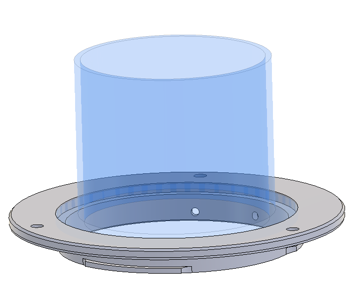
The Verkstan design works with off-the-shelf clear folder covers or overhead transparencies. You punch them in a specific pattern with a standard 3-hole punch, and they fit right onto the frame. (They have different designs, because the media size and hole punch patterns vary by country.)

I used one of these shields for a couple of days during a woodworking project, and I found it to be light and comfortable. After a few minutes I hardly noticed it.


I got linked up with a couple of local groups that organized through Facebook. A lot happened in a short time regarding designs, materials, printing methods, throughput, standards that hospitals would accept, distribution, and volunteer organizations. Fortunately the group I joined had also settled on the Verkstan design, which made assembly and distribution a lot easier!

I did not blog about this at the time. Our focus was on quickly producing large volumes of acceptable products. Now that it's settled down, here's a summary of the main points.

From March 26 through June 13 I printed 405 frames, and packaged some of them with punched shields. I gave a few to hospitals directly, but most went through the FB organization. Since my company had us working from home, and eventually furloughed, I was home to keep this little "factory" going. (At the same time, my wife was mass producing cloth face masks for a couple of hospitals.)

I printed with 12 varieties of PLA and PET-G, and a new material called Orbium. I used up most of the PLA and PET-G that I had on hand, and bought a few rolls. At times it became hard to find filament on Amazon and at Micro Center. About that same time, my local Fry's electronics closed. (The Orbium was donated to the group, and I used a couple rolls of it.)

I have always kept track of my print jobs and settings, and what works and what fails. I improved my tracking so I could use a pivot table to see which materials worked better statistically. The oldest spools (it came with my printer) had a dismal 17% success rate... old and brittle. Most had a 50% to 90% yield. Inland PLA White yielded 96%, and CC3D PLA Max Yellow was 100% successful.


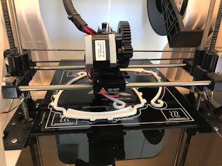
Because we were trying to produce a lot quickly, we worked on arrangements to fit multiple frames on the bed at the same time. With my printer's size, the most I could get at a time was two. Someone split the frame into two parts, which could nest a lot more onto a bed, but I was concerned about assembly and breakage, so I stuck with the single design, 2 to a run.


The other aspect was post-processing. All frames needed some cleanup of "nubs" so they would be comfortable to wear. Some products printed much cleaner than others. I made a *lot* of little tweaks within my slicing software, to reduce the amount of Dremel work per frame.


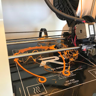
My heated bed has cold areas, and often the parts at the edges would come loose, spoiling a run. Running the machine day and night, the most I produced in one day was 19 frames. 9 to 15 per day was more common. I eventually added some "ears", a little extended skirt that helped some of the narrower parts stick to the bed better.


Some people were able to use a vertical "stack" design which allowed them to print 5 to 10 or more in one run, and then pop them apart. I tried some of their designs, and I tried some of my own. I could never find spacing and settings that would allow the multiple frames to come apart. They were always hopelessly bonded together. So I reverted to 2 at a time, and with some finicky filaments I just ran 1 at a time.

In late June, the OC group announced that they demand for 3D printed PPE had decreased enough that we could cease operations. The supply of commercial products had caught up with demand.