Tuesday, November 19, 2019

Telescope eyepiece adapter for Micro Four Thirds camera

I have a Meade reflector telescope which I haven't used in years. Back when I did use it, I had a Nikon DLSR which was really too big and heavy to even try to use on the scope. Even if the weight did not overwhelm the star tracking motors, the scope has enough "play" in the tripod and mechanisms that I figured it would be a pain to try to align. I never really looked into it back then.

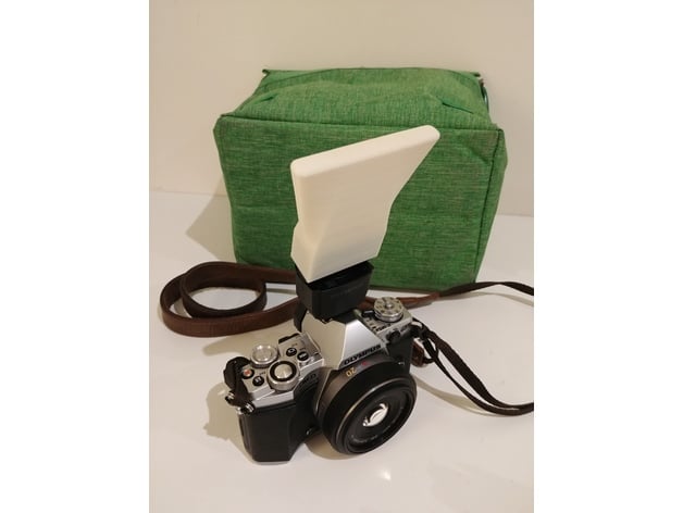
A few months ago I got an Olympus OM-D E-M5 Mark II mirrorless camera. It's like a DSLR, but much smaller and lighter. I learned that some of its advanced features make it suitable for astrophotography, so I figured I'd check into it. One way to mount it is called "prime focus", and place the camera where the eyepiece (final lens) would go. The image forms directly on the camera sensor. The telescope essentially becomes a huge lens for the camera. So an adapter is needed that will fit into the lens mount on the camera, and slide into the focusing unit on the scope.

This camera is built around a specification named "Micro Four Thirds", and other makers such as Nikon, Canon, etc. all make them. I figured someone would have designed a prime focus telescope adapter for MFT, and sure enough I found one to download on Thingiverse, contributed by Nikolaus Spence. Cool! It printed easily. Then... I found that my entry-level telescope has a smaller eyepiece adapter than most. Mine needs a 1" diameter, and the download was a 1 1/4" and not parametric (changeable). Bummer! It looked like I'd have to design my own.

The problem is, the "bayonet" connectors for camera lenses are *very* specific and would be rather difficult to recreate. They look like three equally-spaced lobes around a circle, but they are not equal, so a lens can only go on one way. The tolerances are pretty tight. I reached out to Olympus to get the spec, but they don't give it out for free - it's only available to participating manufacturers.

I found a set of reverse-engineered CAD files on a site called Salvaged Circuitry, contributed by Anthony Kouttron. It included drawings, but even better, 3D shape files I could actually import into Fusion 360.


The shape was for both the bayonet mount that goes in the camera, and a flat flange with screw holes that would attach to a lens or whatever. I did not need the flange, so I used a construction plane and sliced it off, leaving just the bayonet mount.


Then I made a cylinder of the size needed to go into the telescope focuser, and joined it to the bayonet mount with cylinders. From the Thingiverse part I got the idea to make fine threads on the inside of the cylinder, to try to absorb any stray light rather than reflecting it.

Print 1:

The cylinder was too thin, and the attachment to the camera base too weak. It broke right away.


Print 2:

I thickened the cylinder and added a fillet at the joint. This one was more solid, fit into the telescope, and fit into the camera mount after a little cleanup. But it didn't latch into the camera when turned to the right point... it kind of jams in place after turning further. There must be something not quite right in the design or the print. But it works!


I tried it on my telescope one night with a clear sky and a nice moon. I found that the focuser-adapter-camera setup did not travel quite far enough inward to achieve focus. I had read about this issue. The way to solve it is to add a Barlow lens, a short tube with a lens that adds magnification and changes the focal length. My scope came with a 3x Barlow, and it worked well. I was afraid the extra length and the weight of the camera would make the setup bend or slop around, but it was solid. I was then able to focus the image, though it was quite tricky. Here's one of the best shots from that night.


Later I noticed that the first layer(s) had not printed perfectly; one of the bayonet mount lobes was kind of lifted up and not filled well. I also thought that maybe the thickness of the lobes was not quite right and might be the reason the camera doesn't latch it. So...


Print 3:
Some time ago I had bought a set of different sized nozzle extruders for my 3D printer. The standard size for this kind of printing is 0.4mm. I had had limited success printing with another project with a 0.25mm nozzle, but I think part of that problem was the filament. This KVP PLA extrudes really smoothly, so I figured I'd go all the way down the the 0.15mm nozzle. The problem with tiny nozzles is they take longer to print, but this is a small part. At 0.4 it took just over an hour, and at 0.15 about 2:20, which is certainly reasonable. It printed very nicely - no clogs, but a *lot* of tiny hairs inside to clean up. I don't want plastic bits falling down into the telescope.

Print 4:
While #3 was printing, I had an Aha! moment. Maybe the reason I could not reach focus with the adapter was the fillet I added at the bottom of the cylinder. Maybe without that extra 0.1 inch, it would go down far enough to reach focus at infinity. I let #3 finish, then I hid that fillet, exported it and printed it again. Each part only costs 9 cents to print, so why not! Since I had thickened the cylinder at the same time as I had added the fillet I figured it would be strong enough. It is.


Now I need to wait for the moon to come back on a clear night. Maybe before then I'll try it during the daytime on terrestrial targets. After I test it out I'll upload it to Thingiverse and send thank-you's to Nikolaus and Anthony, and tell the folks on the Micro Four Thirds forums.

Update 2020-07-03: I finally got to test this out. The base is too thin, but with some paper shims I got it to work for now. Here is tonight's full moon:

Update 2020-07-18: I figured out how much thickness I needed to add to the base but found that the 3D file for the connector plate I had started with was not changeable. It was imported into Fusion 360 in a mode which precluded changing the thickness parametrically. I ended up redesigning the whole thing from scratch, using the dimensions from the diagram. After a couple of cycles of test-and-adjust I got a version which fits pretty snugly in the camera. The camera socket does not latch on to it, so it depends on friction. It would be better if I could make a version that securely locks in.

I tested this version and photographed Jupiter and Saturn over a couple of nights. (Not great photo quality due to a lot of atmospheric turbulence. I'll get there.) I think I hit the focus limit once, but that could be resolved by backing it out of the eyepiece tube a bit.


Now that I have a working version I shared the files on Thingiverse at https://www.thingiverse.com/thing:4546246

Monday, November 18, 2019

Elephant drainer version 2

I wanted to make an elephant drainer for my daughter. Her sink has a bit of a lip, and the current elephant's trunk lays flat on the surface. If the trunk sat on the lip, it would tilt the whole thing backwards and would not drain. So I revisited the design in Fusion 360 and lifted the trunk upward. Unfortunately that meant I needed to recreate the hole through the trunk. I printed a sample of the bottom part and found it needed to be lifted more. It was difficult to reshape it any more, so instead I rotated the front legs down, lifting the head and body off the ground. The downside of that is that it then required support structures under the whole belly, head, and trunk. That would take more time and plastic, but I went ahead with that design.

I thought I had enough of the nice silver (actually gray) PET-G filament, but it ran out about two-thirds of the way up.


It would look funny, and the divider is designed for the full height. So... I guess I have a flowerpot (with drainage).


Unfortunately Micro Center no longer stocks that PET-G silver, which is too bad because it really prints nicely. I went on line and found eSUN Silk PLA. I printed this helix as a test. Look how silky smooth and shiny!


But that test object prints in one continuous smooth curve. No stops and starts. In real life I had a lot of problems with globs and gaps. I messed around a lot with temperature, retraction, etc. trying to improve it. I don't really remember the solution, but it eventually smoothed out a bit.


Failures #1 and 2 were that it did not stick well to the bed.


Failures #3, 4, and 5 were that it would fail to feed, causing skips large and small. The small skips just caused unattractive dark lines of missing filament, visible on the side just above the top of the leg. The large skips caused subsequent layers to fail to adhere completely!

I used up the whole spool of filament and never got a successful print. I posted my experience in the review section for the product on Amazon.


Back to Micro Center for an alternative gray. They had Inland PLA+ Silver which looked pretty good. It's actually gray, slightly shinier than the Inland PET-G.  Rather than start out with the elephant, I printed several test cubes and cylinders. It took some futzing, cleaning and lubing of my machine, adjusting temperature, speed, and extrusion width to get a clean print. Were those adjustments the cause of the failures on the eSUN Silk? I don't think so... I think the eSUN Silk had variations in the density or melting point, causing it to temporarily clog and then restart printing.

I had one early adhesion failure, which was fixed by reapplying Magigoo. I eventually got a completed print.

So what is PLA+ ? Apparently it can mean whatever the manufacturer wants it to mean. Different filaments have different additives. In this case, the final product is *really* tough. The divider needs to be bent a bit to insert it, and I had to print it thinner than usual to have any hope of bending it enough.

Ironically, from hints on the Internet and in the packaging, it seems that Micro Center's "Inland" house brand is produced by eSUN. So the PET-G I liked, and the PLA Silk I hated, and the PLA+ I eventually used, with different results, are all eSUN products.

It's not as smooth as the Inland PET-G, but not too bad. And as my wife pointed out, real elephants aren't exactly smooth.


Sunday, September 22, 2019

QuilterCam

My wife is a quilter. She has a Long-Arm Quilting Machine for stitching together the top, batting, and back of quilts up to 10 feet wide.

It can be run manually, but it also has a computer drive mechanism so it can do preprogrammed patterns, doing a strip about 1 foot wide at a time. It's possible for the thread tension to be incorrect or go out of whack, causing the stitches to be uneven or "looped", mainly on the bottom side where it can't be seen easily. In that case one needs to stop it promptly and rip out the ugly stuff.

Since I had previously set up a Wyze camera to monitor my 3D printer from afar, we came up with the idea of having a camera show the bottom view of the quilter, to keep an eye on the stitching quality. But since the quilts can be up to 10 feet wide, a single camera won't show the whole area. So I'm working on a bracket to mount the camera to the bottom of the mechanism, so it will follow along and show the area just stitched.

The bracket needs to fasten onto the mechanism tightly because it's going to be moving around quickly. But it needs to be removable too. Fortunately there are a couple of holes conveniently placed on the bobbin arm.


I designed this angled plug on the end of some slightly flexible arms, to make what I call a "clip" that snaps onto the bobbin arm.

It took quite a few iterations to get the clip dimensions and stiffness correct. Fortunately I was able to print "slices" instead of printing the whole part.


Here's how it looks installed.

The bracket needs to be stiff in the X and Y dimensions, because the quilter head will be moving around quickly. But it does not move up and down, so stiffness in the Z dimension is not so important. In an earlier iteration I had the bracket extend beyond the clip to have some leverage to keep it from wobbling up and down, but that proved not to be necessary.


It's a large object with parts that go up and down from the central bracket plane, which would be hard to 3D print in one piece and would take a lot of support material. So I print it in two parts and plan to glue them together. At the moment they are held together with double-sided tape.

This went through about 3 or 4 iterations before I figured out a simplified design which needs almost no support material. Each part can be iterated separately.


There are some constraints on the location of the camera. It needs to clear the carriage mechanism in the Y dimension at one extreme, so the bracket can't be too short...


... and needs to clear a roller in the Y and Z dimensions at the other. Since it's so long, it has to slope down.


It needs to place the camera down a bit below the fabric so the camera can focus on it, and a bit to the left to look at the just-stitched area.


The Wyze camera comes with a tilt-swivel mechanism, so I just need to get the camera close to the correct location and angle, and then I can fine-tune it. I think I'll have to fix the tilt-swivel mechanism in place with some removable glue... it's not very stiff.


The camera needs power, and conveniently there is a USB port at the back of the carriage. The power cord is masking-taped in place for now, and when this is all finalized I'll fasten them in place with sticky cable clips.


Next step is to try it in action and see if there are any problems with vibration etc.


Tuesday, September 17, 2019

Diffuser for Olympus FL-LM3 flash


I love Thingiverse! It's a repository for the obscure, but it often has exactly what one needs. I recently got an Olympus camera which came with a tiny external flash. I looked on Thingiverse, and sure enough, someone named Dale Armit in Australia had designed a snap-on diffuser for it.

I downloaded it right away and recently got around to printing it in Inland PLA (white, of course).


The first try did not come out so well. The first few layers had a lot of gaps and failures to adhere. And the rest of it had little gaps as well. It's pretty common to have issues the first time around, and fortunately little things like this don't use much time or plastic: it only used $0.33 of filament. So I changed several settings:

  • Reduced the speed
  • Increased the temperature
  • Measured the actual filament diameter with calipers. It was about 3.5% smaller than the previous filament I used. That doesn't sound like much, but it causes the software to underestimate the amount of plastic to extrude.
  • Checked the fan speed settings.
  • Closed the air conditioning vent in my office, so a blast of cold air would not interfere with adherence.
When you're dealing with fractions of millimeters, these little variations can make all the difference!

I was able to test the fit with this part, and it seems to be just fine. The next iteration is looking good.


LGBTQ+ pronoun add-ons to church name tags

A few months ago we held a workshop on LGBTQ+ topics at our church and one topic was how to let people know what to call you - what pronouns you use.  Some people have started to use little buttons or stickers that say she/her/hers, or whatever they prefer. An important aspect is that not only LGBTQ+ people can wear them, but "allies" can wear them too. That helps prevent anyone from feeling singled out, and communicates that you are LGBTQ+ friendly!

At the end of that workshop my wife and I came up with the idea of making standard pronoun name-tags available for people to use at church, that would look like and blend in with our regular nametags, to normalize the idea.  We developed the idea of a magnetic pronoun tag that would attach to our regular nametags. We are not the first or only church with this idea. A small but growing number of churches and temples around the country are starting to do something like this. 


It had to be just the right thickness to bring the pronoun part "up" to match the level of the name tag part. And the dimensions would need to specifically match the name tags that we buy. We learned that regular badge-makers could not produce such a product. They work with flat sheets of plastic and we needed a 3-dimensional part. So 3D printing was the natural solution.


They would be optional (not everyone will want one), and removable (because people may not be comfortable wearing them all the time) and changeable (because people's gender identity and/or choice of pronoun can change over time, or even day to day). We 3D printed some samples and wore them for a couple of months, in various places to get people’s reactions and spread the idea. 


The great thing about 3D printing is the ability to quickly try out designs. I tried just a plastic back that would go between the name tag (which has a magnetic plate) and the "backer" that has three magnets, so it would be clamped between. That was not secure enough, so I decided the add-on needed magnets too, so it became a sandwich. 


The lettering on the prototypes did not come out very well. I wanted to use a very small nozzle to get finer details, but I knew that would make the rest of the part take a long time to print. I used a filament-switching technique I've learned, to print the main part in black and the front part in white, with the letters "cut out" to let the black show through. It was good enough for a prototype.


Once we had worked out the details, we contacted our badge maker and arranged to have the pronoun parts professionally made in the right size to work with the add-on.

Next I worked on mass-producing them. I worked out a layout that would let me put 15 to 20 at a time on the print bed.

Unfortunately the heating of the bed is not uniform, and the parts in the back and corners would not stick, and would curl up. I eventually settled on an arrangement of 15 at a time. (This being PLA, we were able to rescue some of the curled ones by pressing them with an iron.)


We bought magnets on line and glued them to the back with superglue because the bond needed to be strong. Kind of tricky, and messy at times. I used the regular "backers" on the other side of the parts to align the magnets and keep them in place while drying. Then we glued the pronoun plates to the front with Goop because that does not need to be strong, and if it ever becomes necessary to pull them off for some reason, Goop is relatively peelable.

We produced 130 of these and have made them available at church. They're a big hit!

Bracelets for hair rubber bands

I printed a couple of these bracelets for my daughter. They have a groove in the middle designed to hold a hair rubber band, which is really helpful when you have little daughters!

The design is from Lance Jenkins on Thingiverse. I printed one in Proto-Pasta Mermaid's Tale, an opaque teal (her favorite color) with mica flakes. The other is in a pink PET-G which is translucent and catches the light in a sparkly effect.

Both printed fine the first time. I keep a spreadsheet listing nearly all of my print jobs, with details of most of the settings I used. That way I can look back at other prints with a particular filament and see what worked.

Thursday, June 6, 2019

Replicating a bicycle part


My bike stopped shifting correctly. I found that a plastic cable guide on the bottom of the crank housing had broken. I could not find a part like it on line, so naturally I figured I’d make one.

It’s pretty small, so I used digital calipers to take lots of measurements so I could design the whole thing parametrically.


For strength it should be printed horizontally, and the bottom is curved, so obviously it was going to need lots of support.

To keep the friction low and to prevent it from fracturing I figured it would be better to use Nylon than PLA. I have a spool of Taulman Bridge in black.

On the first try some holes were too small so I had to adjust them, which was not a problem because it only took a half hour to print.  The second one was better, but both of them had layering problems and drooping edges. So I bumped up the temperature and provided a lot more support. I also went to a low layer height of 0.2 mm and slower slower print speed to get finer features.

The third print was clean enough on top but had some porous areas underneath. I decided that would not matter, so the part should be good enough for its purpose.


Here it is installed.


It seems that I mis-measured or mis-drew the large internal curve. It doesn't lay down against the crank tube properly. But there does not seem to be any vertical force on that area, so I think it will be OK. I'll try it for a while and then check it. If necessary I'll tweak that number and reprint it. That's the cool thing about parametric design in Fusion 360: no need to redraw the whole thing if you just need to change one factor.


Saturday, February 23, 2019

Twisted, melted vase

A design called Twisted, melted vase by Neil Fusillo caught my eye on Thingiverse. I liked the translucent print, and it seemed like something big but not dense that I could print. It's not really melted and twisted, but it looks that way. The outside is ribbed, and a gentle swirl turns into an extreme distortion and then back again. My printer can go up to 200mm (7 7/8") high. It's provided as an STL file ready to print, so no opportunity to change it - probably created with MathCAD or some math-based design program. Even though it's not my design there are a number of decisions to make in order to print it successfully.

I have some translucent PET-G in green and magenta that should look nice and transmit light.

There was not a lot of detail about how to print it, so I did some half-scale samples. The provided file is a solid, i.e. the top is closed off, so I learned how to chop a couple millimeters off with Simplify3D. That makes it an open shell, but the thickness of the shell would be up to me. With three layers it was forecast to take 12 hours to print the full size, with 2 layers about 8 hours. So I did my test print at 2 layers.

My concern was that 2 layers might leave little gaps which would not be watertight. But 3 layers would not transmit quite as much light and make it less "glittery". I also wondered whether 2 layers would be strong enough in general. That turned out not to be a concern. This PET-G is slightly flexible but tough. With the glittery look you would think it would be brittle, but it's not at all.

Sure enough, the 2 layer print leaked like crazy. So I did a 3-layer half-high and tested again. This time it had just one little gap. I bought some acrylic to spray on the inside and hopefully make it much more solid. I divided the slicer settings so the bottom part is 3 layers and then it switches to 2 layers in the upper section. I printed one of these, sprayed 3 or 4 layers of acrylic, and then it was perfectly watertight. Maybe these little ones will become pencil holders.

This is the biggest thing I've ever printed. It took 13 hours and 14 minutes. It came out great, just one tiny blob flaw. I'll spray it with acrylic and then test whether it's waterproof.