Sunday, September 22, 2019

QuilterCam

My wife is a quilter. She has a Long-Arm Quilting Machine for stitching together the top, batting, and back of quilts up to 10 feet wide.

It can be run manually, but it also has a computer drive mechanism so it can do preprogrammed patterns, doing a strip about 1 foot wide at a time. It's possible for the thread tension to be incorrect or go out of whack, causing the stitches to be uneven or "looped", mainly on the bottom side where it can't be seen easily. In that case one needs to stop it promptly and rip out the ugly stuff.

Since I had previously set up a Wyze camera to monitor my 3D printer from afar, we came up with the idea of having a camera show the bottom view of the quilter, to keep an eye on the stitching quality. But since the quilts can be up to 10 feet wide, a single camera won't show the whole area. So I'm working on a bracket to mount the camera to the bottom of the mechanism, so it will follow along and show the area just stitched.

The bracket needs to fasten onto the mechanism tightly because it's going to be moving around quickly. But it needs to be removable too. Fortunately there are a couple of holes conveniently placed on the bobbin arm.


I designed this angled plug on the end of some slightly flexible arms, to make what I call a "clip" that snaps onto the bobbin arm.

It took quite a few iterations to get the clip dimensions and stiffness correct. Fortunately I was able to print "slices" instead of printing the whole part.


Here's how it looks installed.

The bracket needs to be stiff in the X and Y dimensions, because the quilter head will be moving around quickly. But it does not move up and down, so stiffness in the Z dimension is not so important. In an earlier iteration I had the bracket extend beyond the clip to have some leverage to keep it from wobbling up and down, but that proved not to be necessary.


It's a large object with parts that go up and down from the central bracket plane, which would be hard to 3D print in one piece and would take a lot of support material. So I print it in two parts and plan to glue them together. At the moment they are held together with double-sided tape.

This went through about 3 or 4 iterations before I figured out a simplified design which needs almost no support material. Each part can be iterated separately.


There are some constraints on the location of the camera. It needs to clear the carriage mechanism in the Y dimension at one extreme, so the bracket can't be too short...


... and needs to clear a roller in the Y and Z dimensions at the other. Since it's so long, it has to slope down.


It needs to place the camera down a bit below the fabric so the camera can focus on it, and a bit to the left to look at the just-stitched area.


The Wyze camera comes with a tilt-swivel mechanism, so I just need to get the camera close to the correct location and angle, and then I can fine-tune it. I think I'll have to fix the tilt-swivel mechanism in place with some removable glue... it's not very stiff.


The camera needs power, and conveniently there is a USB port at the back of the carriage. The power cord is masking-taped in place for now, and when this is all finalized I'll fasten them in place with sticky cable clips.


Next step is to try it in action and see if there are any problems with vibration etc.


Tuesday, September 17, 2019

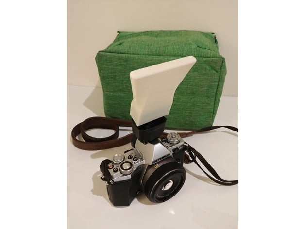
Diffuser for Olympus FL-LM3 flash


I love Thingiverse! It's a repository for the obscure, but it often has exactly what one needs. I recently got an Olympus camera which came with a tiny external flash. I looked on Thingiverse, and sure enough, someone named Dale Armit in Australia had designed a snap-on diffuser for it.

I downloaded it right away and recently got around to printing it in Inland PLA (white, of course).


The first try did not come out so well. The first few layers had a lot of gaps and failures to adhere. And the rest of it had little gaps as well. It's pretty common to have issues the first time around, and fortunately little things like this don't use much time or plastic: it only used $0.33 of filament. So I changed several settings:

  • Reduced the speed
  • Increased the temperature
  • Measured the actual filament diameter with calipers. It was about 3.5% smaller than the previous filament I used. That doesn't sound like much, but it causes the software to underestimate the amount of plastic to extrude.
  • Checked the fan speed settings.
  • Closed the air conditioning vent in my office, so a blast of cold air would not interfere with adherence.
When you're dealing with fractions of millimeters, these little variations can make all the difference!

I was able to test the fit with this part, and it seems to be just fine. The next iteration is looking good.


LGBTQ+ pronoun add-ons to church name tags

A few months ago we held a workshop on LGBTQ+ topics at our church and one topic was how to let people know what to call you - what pronouns you use.  Some people have started to use little buttons or stickers that say she/her/hers, or whatever they prefer. An important aspect is that not only LGBTQ+ people can wear them, but "allies" can wear them too. That helps prevent anyone from feeling singled out, and communicates that you are LGBTQ+ friendly!

At the end of that workshop my wife and I came up with the idea of making standard pronoun name-tags available for people to use at church, that would look like and blend in with our regular nametags, to normalize the idea.  We developed the idea of a magnetic pronoun tag that would attach to our regular nametags. We are not the first or only church with this idea. A small but growing number of churches and temples around the country are starting to do something like this. 


It had to be just the right thickness to bring the pronoun part "up" to match the level of the name tag part. And the dimensions would need to specifically match the name tags that we buy. We learned that regular badge-makers could not produce such a product. They work with flat sheets of plastic and we needed a 3-dimensional part. So 3D printing was the natural solution.


They would be optional (not everyone will want one), and removable (because people may not be comfortable wearing them all the time) and changeable (because people's gender identity and/or choice of pronoun can change over time, or even day to day). We 3D printed some samples and wore them for a couple of months, in various places to get people’s reactions and spread the idea. 


The great thing about 3D printing is the ability to quickly try out designs. I tried just a plastic back that would go between the name tag (which has a magnetic plate) and the "backer" that has three magnets, so it would be clamped between. That was not secure enough, so I decided the add-on needed magnets too, so it became a sandwich. 


The lettering on the prototypes did not come out very well. I wanted to use a very small nozzle to get finer details, but I knew that would make the rest of the part take a long time to print. I used a filament-switching technique I've learned, to print the main part in black and the front part in white, with the letters "cut out" to let the black show through. It was good enough for a prototype.


Once we had worked out the details, we contacted our badge maker and arranged to have the pronoun parts professionally made in the right size to work with the add-on.

Next I worked on mass-producing them. I worked out a layout that would let me put 15 to 20 at a time on the print bed.

Unfortunately the heating of the bed is not uniform, and the parts in the back and corners would not stick, and would curl up. I eventually settled on an arrangement of 15 at a time. (This being PLA, we were able to rescue some of the curled ones by pressing them with an iron.)


We bought magnets on line and glued them to the back with superglue because the bond needed to be strong. Kind of tricky, and messy at times. I used the regular "backers" on the other side of the parts to align the magnets and keep them in place while drying. Then we glued the pronoun plates to the front with Goop because that does not need to be strong, and if it ever becomes necessary to pull them off for some reason, Goop is relatively peelable.

We produced 130 of these and have made them available at church. They're a big hit!

Bracelets for hair rubber bands

I printed a couple of these bracelets for my daughter. They have a groove in the middle designed to hold a hair rubber band, which is really helpful when you have little daughters!

The design is from Lance Jenkins on Thingiverse. I printed one in Proto-Pasta Mermaid's Tale, an opaque teal (her favorite color) with mica flakes. The other is in a pink PET-G which is translucent and catches the light in a sparkly effect.

Both printed fine the first time. I keep a spreadsheet listing nearly all of my print jobs, with details of most of the settings I used. That way I can look back at other prints with a particular filament and see what worked.

Thursday, June 6, 2019

Replicating a bicycle part


My bike stopped shifting correctly. I found that a plastic cable guide on the bottom of the crank housing had broken. I could not find a part like it on line, so naturally I figured I’d make one.

It’s pretty small, so I used digital calipers to take lots of measurements so I could design the whole thing parametrically.


For strength it should be printed horizontally, and the bottom is curved, so obviously it was going to need lots of support.

To keep the friction low and to prevent it from fracturing I figured it would be better to use Nylon than PLA. I have a spool of Taulman Bridge in black.

On the first try some holes were too small so I had to adjust them, which was not a problem because it only took a half hour to print.  The second one was better, but both of them had layering problems and drooping edges. So I bumped up the temperature and provided a lot more support. I also went to a low layer height of 0.2 mm and slower slower print speed to get finer features.

The third print was clean enough on top but had some porous areas underneath. I decided that would not matter, so the part should be good enough for its purpose.


Here it is installed.


It seems that I mis-measured or mis-drew the large internal curve. It doesn't lay down against the crank tube properly. But there does not seem to be any vertical force on that area, so I think it will be OK. I'll try it for a while and then check it. If necessary I'll tweak that number and reprint it. That's the cool thing about parametric design in Fusion 360: no need to redraw the whole thing if you just need to change one factor.


Saturday, February 23, 2019

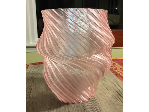
Twisted, melted vase

A design called Twisted, melted vase by Neil Fusillo caught my eye on Thingiverse. I liked the translucent print, and it seemed like something big but not dense that I could print. It's not really melted and twisted, but it looks that way. The outside is ribbed, and a gentle swirl turns into an extreme distortion and then back again. My printer can go up to 200mm (7 7/8") high. It's provided as an STL file ready to print, so no opportunity to change it - probably created with MathCAD or some math-based design program. Even though it's not my design there are a number of decisions to make in order to print it successfully.

I have some translucent PET-G in green and magenta that should look nice and transmit light.

There was not a lot of detail about how to print it, so I did some half-scale samples. The provided file is a solid, i.e. the top is closed off, so I learned how to chop a couple millimeters off with Simplify3D. That makes it an open shell, but the thickness of the shell would be up to me. With three layers it was forecast to take 12 hours to print the full size, with 2 layers about 8 hours. So I did my test print at 2 layers.

My concern was that 2 layers might leave little gaps which would not be watertight. But 3 layers would not transmit quite as much light and make it less "glittery". I also wondered whether 2 layers would be strong enough in general. That turned out not to be a concern. This PET-G is slightly flexible but tough. With the glittery look you would think it would be brittle, but it's not at all.

Sure enough, the 2 layer print leaked like crazy. So I did a 3-layer half-high and tested again. This time it had just one little gap. I bought some acrylic to spray on the inside and hopefully make it much more solid. I divided the slicer settings so the bottom part is 3 layers and then it switches to 2 layers in the upper section. I printed one of these, sprayed 3 or 4 layers of acrylic, and then it was perfectly watertight. Maybe these little ones will become pencil holders.

This is the biggest thing I've ever printed. It took 13 hours and 14 minutes. It came out great, just one tiny blob flaw. I'll spray it with acrylic and then test whether it's waterproof.


Friday, February 8, 2019

Relief picture - Part 2

The Pink Layer

I could not find any rose-colored filament on line or at my local store. So I decided to try a method I had read about: coloring filament with a Sharpie pen. The idea is that you hold a pen against the filament before it goes into the print head. So I bought some light pink PLA filament and some black, brown, and gold pens.

I downloaded a pen-holding device from Thingiverse and printed it. The filament goes in the top, rubs on the pens, and comes out the bottom. Unfortunately it did not work with the design of my printer because the filament goes up and then down into the top of the housing. I stuck the holder to the housing, but it just put way too much stress on the filament and caused it to fail to feed. This would work with a printer where the filament feeds straight down, but I can't use it..


So I held the pen by hand on some test prints. I really didn't want a lot of color, I wanted it to be kind of blotchy like the watercolor aura. With the concentric top layer I used, and coloring several inches of filament, the color goes round and round and makes an agate-like layered pattern. And the heating / mixing of the ink came out kind of unexpectedly: black turned to purple. Brown came out kind of orange-brown. Gold glitter didn't seem to do much at all. (The irregular black line is one I drew later for another purpose.) This might be useful in some future project but it's not what I was going for.


I decided I could work with this by using very intermittent dots of brown ink which turned into a rather light halo. Small dots of ink smear out into lines, and if they are small enough then the lines kind of come and go irregularly as the head goes around. Here's a view of the final effect. Not quite the rose color I was hoping for, but somewhat random and far better than the intense pink PET-G.


The final print

I wanted to print it as large as my printer would allow, which worked out to about 8" x 6.5". But I had noticed before that certain large prints didn't stick well everywhere on the bed, due to uneven heating. This time I decided to produce a heat map. I laid a piece of paper on the bed, set it to 60 degrees Celsius, and used a a laser thermometer to measure different areas. (The paper may have blocked some of the heat.) I didn't record a temp at every location, but quite a few. In this diagram (Excel Conditional Formatting!) the bold numbers were measured and the italics are averages of the surrounding measurements. The black box is the official "hot zone" where printing happens.

So I made sure to use a fresh, complete coating of Magigoo. The wood background plate did fail to stick at the top and curled up a bit, but it's hardly noticeable. Other than that, the print went pretty well. It took about 7 hours, and all the filament changes went well.


Lettering

Since the new pink is PLA instead of PET-G, it stuck better to the layers above and below. But the final black layer on top of the lettering was pretty narrow and didn't really extrude enough. So there were big gaps in the final lettering. There was no way to go back and reprint just that bit, but I realized a 3D pen might just do the trick. I know people use them to create solid objects in thin air, and 3D printing people use them to join multi-part prints together. I figured it would work to touch up the black on the letters.

I settled on the Mynt3D Professional pen and ordered one from Amazon. I practiced drawing a few objects and letters on glass and on an early sample of the wood PLA to get the hang of it before working on the final picture. The main issue is that you're "painting" with filament in real time, and it's only as accurate as your hand is steady. So with some practice and choosing the right extrusion speed it worked out OK, especially since this project was hand-drawn to begin with. In a more straight and smooth project, maybe not so much. I also used it to fill in a couple places where the Mermaid Tail had some gaps.

Final result

Here are three images of the final piece, lit from different angles so you can see how the light plays on the glitter in the parts with different top-level orientations.


And the final result, framed and ready to give to my grandkid.


Saturday, January 12, 2019

Relief picture - Part 1

My current project is to create a 3D representation of a watercolor drawing done by one of my grandkids, turning it into a "relief" piece.

This has been rather difficult, but I'm getting there. I'll describe some of the challenges and how I'm solving them.

Color

A rose color is used as an amorphous background, which I am calling an "aura", with disconnected splotches. It also highlights the lettering. I have a pink PET-G which may work. It is translucent, so if I print varying numbers of layers the underlying colors should allow it to vary a bit.

A greenish-turquoise-bluish-teal color is used for a smaller aura and also to color the main subject. There are distinctly lighter and darker areas. I have a green PET-G but as you'll see below it is too bright. I found an interesting PLA color by Proto-Pasta called Mermaid's Tail, which includes mica flakes to make glitter.

It's on a tan or sepia or vellum background. I have a wood-infused PLA that should work nicely.

With 3D printing filament, the color is pretty much constant. I printed some "swatches" to see how increasing numbers of layers would vary the color.

Pink PET-G over black came out quite reddish. Differing adhesion does give a nice variation to the color. We'll see how it works over wood.

I thought the same idea would work for the teal, but it's really opaque.

But the color swatches revealed a different property of the Mermaid's Tail filament. The apparent brightness (lightness) is affected by the orientation of the top layer. Horizontal reflects the most light. Vertical reflects the least, making it darker. Diagonal orientation gives an intermediate color. I wondered if I could use this property by ensuring that the top printed layer of each part of the main subject matched the desired shade.


Digitizing the watercolor

Working from a digital photo, I used Gimp to pull each color area out into its own image. Like many art programs, Gimp has a "magic wand" which enables you to select areas of a specific color or a range of colors. This took a while. I created images for the rose aura, the teal aura, face, hair, upper right arm, lower right arm, left arm, left hand, right hand, the black central part of the lettering, and the rose outline of the lettering. Also one for the black outlines around the main components.

The magic wand pulls in stray bits around the main subjects, and fails to fill in areas solidly. So I used paint tools in Gimp to clean up and fill in. This is perhaps the most tedious part of the process. There's a balance between enough detail and too much detail. I wanted enough to convey the random sense of the auras, and the hand-drawn feeling of the main subject. But too much detail makes a lot of work for Fusion 360, causing it to slow down.

Fusion 360 wants to import images as SVG (vector) files, but Gimp doesn't export SVG. So I used Inkscape to convert each file from a BMP (bitmap) to SVG. Then I imported each into a separate Sketch and extruded each into a Body. I used parametric modeling so I can vary the thickness of each component as I work on the overall relief.

Contours

When I thought the teal would be translucent, I had spent a lot of time trying to figure out how to vary the colors of the main subject by sloping them in a way that made sense with the relief of the main subject. The biggest problem was that lower right arm needed to vary its thickness in the wrong direction, opposite to the direction it should slope visually. Once I realized the orientation affected the light, I adjusted the thickness of each component so the top layer was oriented correctly. (I did this conceptually in Simplify3D software, not by actually printing it.) This looked to be tedious because of needing to keep track of cumulative thicknesses. Fortunately I found in Simplify3D a setting for "External Infill Angle Offsets". I can pick the exact angle of the top layer of each "process". Nice!

That's assuming the top layer orientation is "Rectilinear". There's also a setting for the top layer infill to be "Concentric", which should great for the auras, making their top surfaces more random in color and/or reflection.

This enabled me to vary the thickness of each component of the main subject without worrying about the exact number of layers. Each component (or group of them) could be a "process" in Simplify3D. So the face is lowest. Then the right upper arm and left arm are a bit thicker. Then the right lower arm. Then the hair. Then the hands.

I had hoped to round off the edges of the arms and hands to make it more realistic and organic. But the complex shape confused the Fillet function in Fusion 360, so I had to give up on that idea.

As I stacked up the image layers in Fusion 360 it became apparent that there were some gaps. So I expanded the black outlines into a solid layer (I called the "profile") above the auras and below the body parts. This ensures everything is solid and won't have any unsupported areas. 

Multiple layers

Simplify3D allows you to change parameters as you work your way up through the thickness of a print. Each group of parameters is called a "Process". I organized the information about the components and their thicknesses into an Excel spreadsheet. This let me see for example that the lines-profile and the black part of the lettering go together. The right upper arm and left arm belong together, both from the relief level and color aspect. It worked out to 9 Processes. I need to change filament colors between Processes 1 through 5, and then Processes 5 through 9 are all the teal filament but with different thicknesses and top layer orientations.

In earlier projects I have learned how best to pause a print to switch filaments. Simplify3D allows for "post processing" commands to alter the file it produces. I added commands to pause for the 4 filament changes, and figured out that all those commands need to be defined in the last process. Kind of weird, but it works. I looked at the GCode file to ensure that it was making the changes in all the right places.

Multiple filament types

The first layer will be wood PLA which prints at 210C, then the pink layer is PET-G at 245C, and then the rest are all PLA at 210C. In the first test print I had some problems with the pink over the wood, but I think that was more about retraction/extrusion than about adhesion. I think the pause for the filament switch needs to be tweaked a bit to ensure the new filament starts flowing fast enough.

Test prints

Because the final product will be big, I've tried some small samples.

This first one was 1/4 scale in X and Y, but regular scale in Z (relief) to test out the multiple filaments. There were some problems with the pink not adhering to the wood. The infill was too sparse at 10%, so the upper layers fell through. Because it was at 1/4 scale, the filament could not keep up with some of the fine features and they got gloppy. I'm hoping that when printed at full size those details will work.

The pink and teal auras were thicker than I intended, so I changed them down to one 0.2mm layer. I'm hoping that will make the pink less intense.

For the next test I set the infill to 15% so the upper layers will not have to "bridge". I tweaked some other settings in the infill area. It also seemed that the filament did not start flowing right away after a change, leaving gaps, so I changed the post-change retract from 0.5mm to 0.2mm.

I printed the next test in just one color, at 100% scale, to see if the larger features print better. I went back to Fusion 360 to select a central rectangle instead of printing the whole picture. Here's a shot from an angle to show the relief.

Next I printed the central rectangle with the multiple filaments. Again the PET-G did not stick to the PLA, and vice versa. That caused the black to fail on the lettering, and other problems. So I guess I'll shop for a rose-colored PLA.

The concentric fill in the thin aura layers looks good - the lower pink and teal areas are blotchy like watercolors.

The "canyons" between the body parts, and the black background at the bottom of them, gives good definition.

The varying top layers on the body parts do make them appear lighter and darker, though that does not come through so well in a photo. They shimmer as you move around.

I also remembered that I didn't copy over many of the disconnected blotches of the rose aura, so I'll need to go back to the images and merge them in.


Saturday, December 1, 2018

Elephant cutlery drainer

Between the product design, the 3D modeling, and the printing, I learn one or more new topics with every project. I worked on this one for more than a month. New tools and techniques included:

  • Initial drawings on iPad with Apple Pencil and Autodesk SketchBook
  • iPad connected to Mac as graphics tablet with Duet
  • Fusion 360's Spline curves
  • Fusion 360's Shell command
  • Fusion 360's Loft command options
  • Fusion 360's Sculpt mode
  • Printing big

Concept & Design

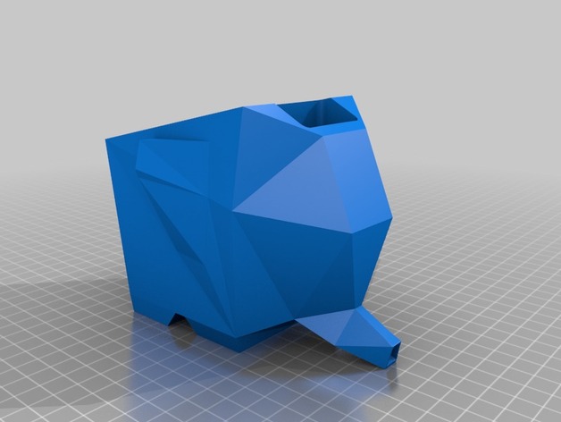
I was looking for a bigger project to print. Most of my projects have been just a few inches in size. But printing large solid objects can take a long time, and as a hobbyist there are limits on the time I can spend babysitting large prints. So I was thinking about large hollow products when I encountered this elephant-shaped cutlery drainer on Thingiverse. It's a useful product, if a bit silly. Water from the draining items shoots from the elephant's trunk into your sink. But I didn't really like the angular appearance of the "low-polygon" method.


I spent a few hours among Asian elephants on a safari in Sri Lanka this year, and elephants have been on my mind. So I decided to try a more realistic, but still stylized, version of the elephant drainer.


Design considerations included:

  1. A large top opening to handle a realistic number of cutlery items
  2. Possibly a divided interior so items would not lay over too much
  3. Low center of gravity and/or wide stance so top-heavy objects would not tip it over
  4. On a real elephant, the trunk starts high on the face and goes downward. In this drainer, the water is going to come from the bottom tips of the objects. The water can't flow up to enter the trunk, so the body and face design needs to give the illusion of a trunk while letting the water enter the bottom of the trunk.
I did not know how I would possibly sculpt the thing from scratch, and most objects I've designed have been basically geometrical, so I envisioned virtually "carving" the body and head from a solid core by cutting it from the side, top, and front using profiles. 


Concept art

I've been playing with Autodesk's SketchBook and Apple Pencil, so I used it to draw multiple profiles. For the top and front profiles I used its mirror function to get a symmetrical profile. I knew that in Fusion 360 I would probably design one side and then mirror the solid object, so I didn't really *need* full drawings, but drawing both sides of the profiles helped make sure it was going to be attractive and what I envisioned.
Side view

Top view. Note that the legs stick out a bit from the body.


Head front view


Rear view


Version 1 - Carved from Three Profiles


I imported the drawings into Fusion 360 and used Spline curves to reproduce them as sketches to use to cut virtual blocks in three directions to form the body, head and trunk. I tried the "duet" application to draw on my iPad as a connected tablet, but ultimately it was easier to use the mouse on the big screen.


I learned to use the Shell feature to hollow out the combined shapes. I added a 5-degree sloped floor and ensured a hole was drilled through the trunk.


I used the Loft feature to join elliptical shapes to form the front and back legs.


I created the whole thing small, so I could print samples relatively quickly. (This elephant is apparently not afraid of mice.)

Ultimately I did not like the result. It was too angular - you can see how the body has places where two different curves join. And there's an artificial-looking "web" under the trunk.

The other problem was that the Shell command has trouble with shapes that have too many complex curves joining. It ultimately failed with my model. So I started over.

Version 2 - Combined Sculpted and Math

I spent some time learning about Fusion 360's Sculpt mode, which works by modifying 3D forms, rather than extruding them from sketches and cutting things. I started with two spheres and pushed and pulled them into more organic shapes for the body and head.

I combined them with mathematical shapes for the legs and trunk.


I also lowered the body closer to the ground to reduce the amount of support material that would be needed.


I didn't like this result either. The short legs and trunk made it look more like a pig than an elephant. So back to the drawing board.


Version 3 - Combined Sculpted Shapes

I thought about making realistic legs to convey the elephant-ness, but bent so the belly would still be on the ground. I found a variety of artwork and sculpture depicting elephants kneeling, and then produced this sketch based on them.

Back in the Sculpt mode, I learned to stretch and bend cylinders: with a single bend for the back leg, and with two bends in the front leg so the foot would be flat on the ground. The legs intentionally crowd the face.


Another cylinder was the basis for the trunk. It's wider at the top and stands out a bit from the face.


I pushed some little dents into the top of the trunk to make it wrinkly-flexible looking. (I got this idea from how they put finger grips in a knife handle in an Fusion 360 instructional video.) You can see that in this shot of the full-size final product being printed.

Here you can also see the support material around the belly, under the legs, and under part of the trunk.


For the eye I went back to how a real elephant looks. I had taken this extraordinary shot of a wild elephant in Sri Lanka.


I traced over the eye in Fusion 360 and turned it into a reverse extrude, essentially a cutout. The shell is thin enough, and the cut deep enough, that it's actually open in places and lets light shine through.


Here's the finished small-size half-body test print. Printing a half-body sample is a great way to see how it's really going to work internally, how things are going to fill in, etc. You can see how I filled in the bottom of the body and trunk with a 5-degree slope for water to flow out.


The Final Print


During the design I had worked with convenient measurements, knowing I could scale it up to maximum size in the slice-print software. I placed it diagonally on the print bed to get the maximum length from legs to trunk. I scaled it up by 210%, resulting in almost 10" total length. The shell started out 0.2 cm thick, so after scaling it is 0.42 cm thick, which is just about right. There's a tradeoff: too thin would not be stiff enough, too thick will increase the print time. This was by far the biggest thing I've ever printed. It took nearly 18 hours!

I chose PET-G filament because it's food-safe, and found a really nice silver-gray.

Unfortunately I forgot one thing: my print bed doesn't heat evenly, plus I think I didn't put enough hairspray at the the very back. So the left rear foot failed to adhere perfectly and curled up. I didn't see it until it was all done, or I might have started over. (Support material is still attached in this shot.) With a little grinding of the irregular parts, it came out OK, it's just kind of lifted in the air.

I also forgot to add a tail!


Here's how it looks in use, with the trunk out over the sink:


I had thought ahead and added slots on the sides to allow for a removable divider, printed separately. This allows objects to stand up straighter.


The divider doesn't go all the way to the bottom, so it doesn't obstruct the drainage.


All in all, I'm quite pleased with how it came out, being my first sculpted project and my first really big print. This is about as big as my Robo3D R1+ can go. Lots of people saw it at our house at Thanksgiving and a couple people asked for copies for Christmas... but at 18 hours per part that may not happen. It's definitely an iterative process. Fortunately printing small-size models saves time and plastic.

I published the design files on Thingiverse here. In the first two weeks over 400 people have downloaded it, but no one has posted a print yet.